
Mechatronics Project - Pinball Machine
Overview
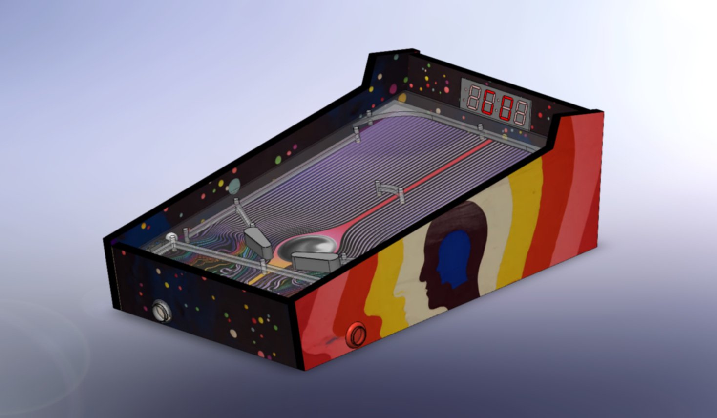
For my Mechatronics course, I was tasked with designing and building an electromechanical system using at least one stepper motor, one additional actuator, and a minimum of two user inputs. My team chose to design a tabletop pinball machine, with solenoid-actuated flippers, an automatic ball launcher, a 7-segment score display, an optical sensor to detect the game’s end, and a custom power supply allowing a single power brick to power these components with varying voltage requirements.


Component Selection
In order to design the circuitry and then write the firmware, the actuators and display hardware had to first be selected. The most critical selections were for the flipper solenoids and the stepper motor that would compress the ball launcher spring. To ensure proper game functionality, these elements would need to have sufficient force to propel the pinball to the top of the playing field. The diagrams shown on the left represent the simple models used in analyzing the system to determine ballpark actuation force and torque for these components.

Firmware
The microcontroller for the project was to be an ATMEL ATMega328P, and our group chose to write all of the code in C. The flowchart shows the general logic of the system, using interrupts for the user inputs (flipper buttons) and the ball drain detection. Since the ATMega only has two hardware interrupts, the signal from the IR sensor was read to the analog comparator, which has an additional interrupt.
SPI was used to communicate with a MAXIM display driver IC, reducing the number of microcontroller pins to control the four digit 7-segment display.